The Mechanics of Power: How Engines Operate|EngineDIY
An engine, also known as an internal combustion engine or simply an engine, is a device that converts chemical energy from fuel into mechanical energy to generate power. It operates based on a precise sequence of steps that enable the conversion of fuel into motion.
Working Principle of an Engine
An engine functions by mixing fuel with air, compressing the mixture, igniting it with a spark, and utilizing the explosive expansion to produce mechanical work. This process follows a cyclical pattern to ensure continuous operation.
Four-Stroke Engine Cycle
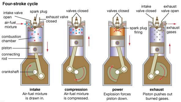
The most common type of engine, the four-stroke engine, operates in the following sequence:
.Intake Stroke: The piston moves downward, drawing in a mixture of fuel and air into the cylinder.
.Compression Stroke: The piston moves upward, compressing the fuel-air mixture to increase efficiency.
.Power (Combustion) Stroke: A spark plug ignites the mixture, causing a controlled explosion that forces the piston downward, generating power.
.Exhaust Stroke: The piston moves upward again, expelling the burnt gases through the exhaust valve.
This cycle repeats continuously, with the flywheel and crankshaft inertia maintaining the engine’s rotation and stability.

Main Components of an Engine
Several key components work together to ensure the efficient operation of an engine:

1. Crankshaft
.The main rotating component that converts the piston's reciprocating motion into rotational energy.
.Comprises a main journal and connecting rod journals to facilitate movement.

2. Cylinder Block
.The core structure of the engine that houses the cylinders where combustion occurs.
.Supports various internal components and enables the power conversion process.

3. Piston and Connecting Rod Assembly
.The piston moves up and down within the cylinder, transmitting force through the connecting rod to the crankshaft.
.The piston rings ensure a tight seal to prevent gas leakage.
.The connecting rod links the piston to the crankshaft, converting linear motion into rotational motion.

4. Cylinder Head
.The cover that seals the top of the cylinder, forming the combustion chamber.
.Provides mounting points for the valve system, spark plugs, and other components.

5. Flywheel
.A rotating mass that stores kinetic energy to ensure a smooth power output.
.Helps the engine maintain a consistent rotational speed and overcome temporary overload conditions.

Assembly Tools and Installation Process
Proper assembly of an engine requires specialized tools and careful installation procedures. Some essential tools include:
.Needle-nose pliers, adjustable wrench, hex screwdrivers (various sizes), slotted screwdriver, hex sockets (8mm, 10mm), and lubricating oil.

Installation Sequence and Torque Settings
.Cylinder Head Screws:
.M3*14: 2 N.m
.M3*12: 1 N.m
.M2.5*6: 0.7 N.m
.M2*7: 0.4 N.m
.Connecting Rod Screws:
.M2*7: 0.7 N.m
.The bolts should be gradually tightened in three steps to ensure even pressure distribution.

Lubrication Points (Example: Twin-Cylinder Engine)
Proper lubrication is essential for smooth engine operation. Key areas include:
.Piston and connecting rod assembly
.Cylinder liner and piston interface
.Crankshaft bearings
.Rocker arms and camshaft lobes

Valve Clearance and Timing
Maintaining correct valve clearance is critical for proper engine operation:
.Ideal clearance: 2mm between the rocker arm and the valve cover.
.Incorrect clearance effects:
.No clearance: Incorrect intake/exhaust timing, preventing the engine from starting.
.Excessive clearance: Unstable engine operation or failure to ignite.

Check each rocker arm according to the above picture.
Crankshaft Crank Throw, Connecting Rod Screws:
When installing the piston connecting rod onto the crank throw, the connecting rod should rotate smoothly on the crank throw. After installation, the crankshaft should rotate smoothly counterclockwise.
Connecting rod screws: M2*7, torque 0.7N·m (apply thread locker).

Timing belt installation follows these steps:
.Align the crankshaft timing mark in a downward vertical position.
.Ensure the piston in the flywheel-end cylinder is at the top dead center (TDC).
.Align the camshaft timing mark vertically downward.
.Install the timing belt and rotate the flywheel counterclockwise two full rotations to confirm alignment.

Engine Startup Procedure
Required Tools for Startup:
.Ignition module, glow plug, starter harness, 3S battery, fuel tank, methanol fuel, fuel tubing, M3 ground screw.
.Spark plug socket (8mm).

Startup Steps:
1. Starter Base Kit: Engine connected to the twin-cylinder base.
2. Starter Accessories Kit: Engine connected to various starting components.

Troubleshooting Common Startup Issues
1. Ignition Failure: Check if the glow plug is receiving power.
2. Fuel Delivery Issue: Ensure the carburetor is drawing fuel properly.
3. Incorrect Timing: Verify timing marks and valve clearance.
4. Insufficient Compression: Check if the engine has adequate cylinder pressure.
5. Carburetor Adjustment: Main needle should be turned out 3.5 turns; secondary needle gap should be 0.5mm.

Conclusion
Understanding how an engine works provides valuable insights into its intricate mechanics and the importance of proper assembly, lubrication, and maintenance. A well-maintained engine ensures reliable performance, making it a crucial component in various applications, from automobiles to mechanical models. By following proper installation procedures and troubleshooting techniques, users can maximize engine efficiency and longevity.
Leave a comment